How a Shaft Design Modification Stopped 10 Failures a Year.
Hi, welcome to all my readers!
In this case study, I will explain how we reduced LT wheel shaft failures in our Quench Car through engineering calculations and practical modifications implemented at our site. I will share the approach we followed to identify the problem, evaluate the shaft design, and implement suitable improvements to improve equipment reliability and prevent recurring failures.
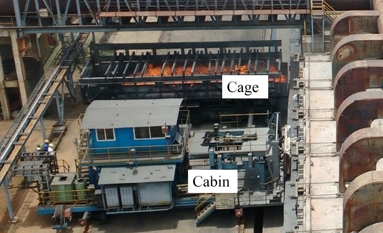
The Quench Car is one of the critical (A Category) equipment items used in the coke oven plant for receiving hot coke from the oven. It is a standalone piece of equipment, and any failure of the Quenching Car will affect production.
- Effective capacity : 45tons
- Running speed : 80m/minutes
- length of carriage : 14000mm
- Tilt angle : 370
- Door open angle : 500
Quench car image:
Scatter plot for Quench car maintenance details in FY 25
| Sl.No | Identified Problem in Quench car | Occurrence | Break down in min. |
| 1 | LT wheel assembly failure | 10 | 765 |
| 2 | cage HR plate damage | 6 | 30 |
| 3 | Cage rope damage | 4 | 60 |
| 4 | cage door lifting rope problem | 2 | 150 |
| 5 | Tie beam problem | 2 | 0 |
| 6 | Alignment plate problem | 2 | 30 |
| 7 | cage door opening problem | 2 | 15 |
| 8 | cage moving cylinder problem | 3 | 120 |
| 9 | cage lifting cylinder problem | 1 | 30 |
| 10 | LT brake failure | 1 | 10 |
Note for Scatter understanding: R² value :
- 0.1 to 0.4 – Weak correlation
- 0.4 to 0.7 – Moderate correlation
- 0.7 to 1.0 – Strong correlation
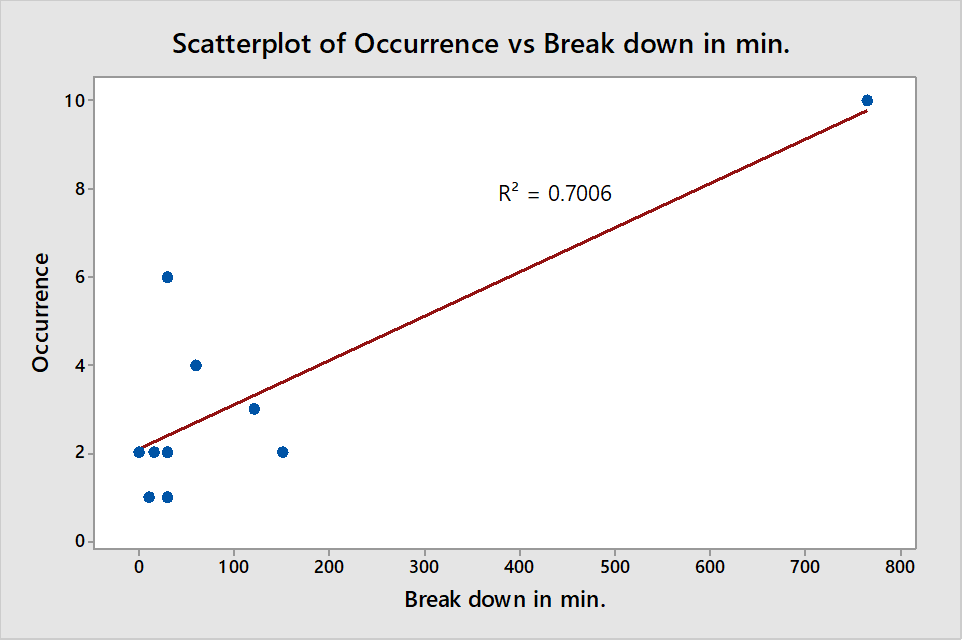
From scatter, Quench car LT wheel failure having strong correlation.
LT shaft shear and LT shaft keyway damage were identified as significant causes of Quench Car LT wheel failures due to their high failure frequency. The failure dates were recorded in our history cards.
The root cause of both LT shaft shear and LT shaft keyway damage was the higher load acting on the wheels during the cage tilting operation.
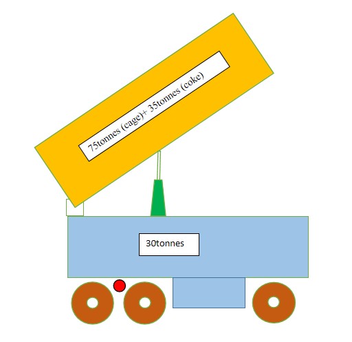
Another one observation was noted, After the quenching process, the Quench Car cage is tilted to drain the water from the cage. Then, the operator operates the Quench Car LT to dump the coke into the wharf. During Quench Car LT movement with the cage in the resting position, the load is distributed across all four LT wheels. During Quench Car LT movement with the cage in the lifted position, the load is carried by only two LT wheels on the west side.
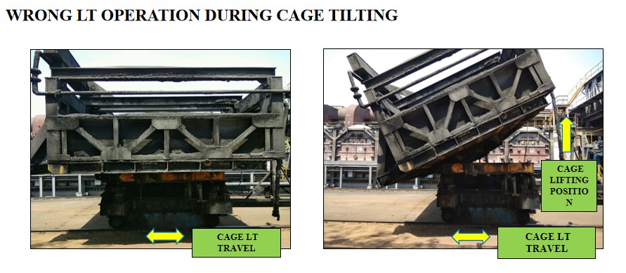
Hence, more load is shared by the west-side LT wheels, which leads to wheel failure. Therefore, this is considered significant.
The existing shaft diameter is 140 mm, and the shaft material is EN09. The Quenching Car cage consists of four wheels. LT shaft shear occurs due to the overload acting on the wheels during the tilting operation.
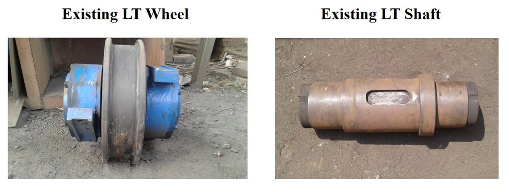
Therefore, we planned to calculate the required shaft diameter under the following conditions:
- During normal running.
- During the cage tilting operation.
Design Calculations:
1. Shaft calculation at the normal running time:
Data:
- Total load: 135 tonnes
- Power: 75×10^3 W
- Speed: 1480 rpm
- Length: 0.320 m
- Material type: EN09
To find:
we have to find the shaft diameter,
Te = (π/16) × Ʈ × d^3
1. Torque transmitted by shaft:
T= (P×60) / (2πN)
= ((75×10^3) × 60) / (2×π×1480)
T= 483.91 N-m.
2. Load carried by single wheel:
W= (135×1000×9.81) / 4
W= 331087.5 N
3. Bending moment:
Mь= W× (L/2)
= 331087.5× (0.320/2)
Mь= 52974 N-m
4. Equivalent twisting moment of shaft:
Te= [Mь^2 + T^2] ˆ ½
= [(52974)^2 + (483.91)^2] ˆ½
= 52976.2102 N-m
Te= 52976210.2 N-mm.
5. Shear stress calculation:
From PSG design data book Pg.no:1.12
For material EN09,
Yield strength (σy) = 460 N/mm^2
Ʈy = σy/2
= 460 / 2
Ʈy = 230 N/mm^2
Factor of safety= 2.3
Ʈ = Ʈy / FOS
= 230/2.3
Ʈ= 100 N/mm^2.
6. Diameter of the shaft:
Te = (π/16) × Ʈ × d^3
52976210.2= (π/16) × 100 × d^3
d^3= 2698056.23
d= 139.22 mm.
d~ 140 mm.
The diameter of the shaft = 140mm.
Shaft Diameter Evaluation:
The existing shaft diameter is 140 mm. During normal operation, the existing 140 mm diameter shaft was found to be satisfactory. However, we observed that excess load acts on the west-side LT wheels during the cage-tilting operation.
Therefore, it was decided to calculate the required shaft diameter for this above case.
2. Shaft calculation during the tilting operation maximum load acts on the west side wheels.
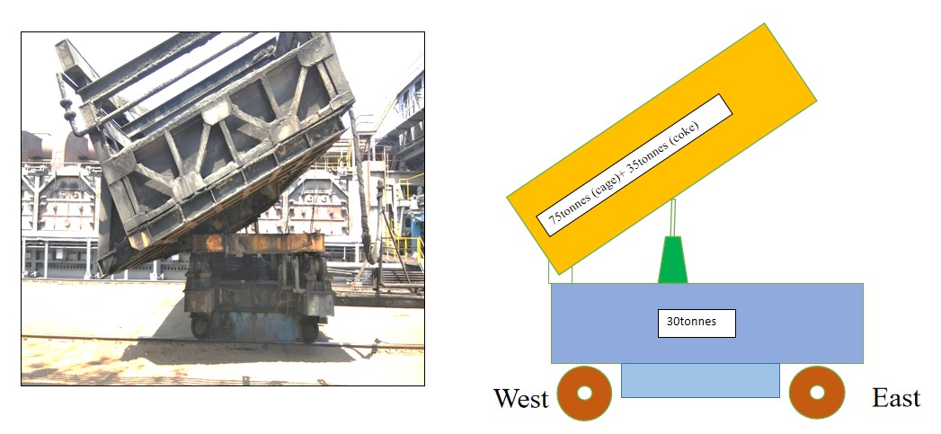
Data:
- Total load: 135 tones
- Power: 75×10^3 W
- Length: 0.320 m
- Speed: 1480 rpm
- Material type: EN09
To find:
we have to find the shaft diameter,
Te = (π/16) × Ʈ × d^3
1. Torque transmitted by shaft:
T= (P×60) / (2πN)
= ((75×10^3) × 60) / (2×π×1480)
T= 483.91 N-m.
2. Load carried by single wheel:
Load acts on 4 wheels: 30tones
Load acts on west side 2 wheels: 70tones +35 tones = 105tones
Load acts on single wheels: (30/4) + (105/2) = 60tones
W= 60×1000×9.81
W= 588600 N
3. Bending moment:
Mь= W× (L/2)
= 588600× (0.320/2)
Mь= 94176 N-m
4. Equivalent twisting moment of shaft:
Te= [Mь^2 + T^2] ˆ ½
= [(94176)^2 + (483.91)^2] ˆ½
= 94177.24328 N-m
Te= 94177243.28 N-mm.
5. Shear stress calculation:
From PSG design data book Pg.no:1.12
For material EN09,
Yield strength (σy) = 460 N/mm^2
Ʈy = σy/2
= 460 / 2
Ʈy = 230 N/mm^2
Factor of safety= 2.3
Ʈ = Ʈy / FOS
= 230/2.3
Ʈ= 100 N/mm^2
6. Diameter of the shaft:
Te = (π/16) × Ʈ × d^3
94177243.28 = (π/16) × 100 × d^3
d^3= 4796407.614
d= 168.65 mm
d~ 170 mm.
Shaft diameter Evaluation:
The required shaft diameter is 170mm during tilting operation. If we increase the shaft diameter, wheel size also need to be increased up to 600mm OD. But this wheel cannot be fixed in existing structure due to space constraint.
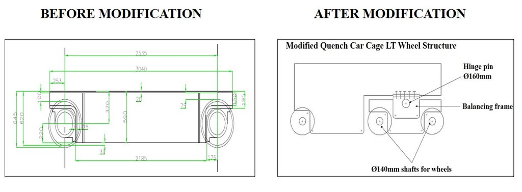
So, we decided to fix the additional wheel on west side for withstand a excess load.
Additional wheel proposals
Proposal-1: Wheel center mounded
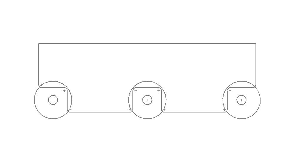
Wheel replacing is too difficult.
Wheel may affect by shock load during LT movement.
Hence it is not feasible
Proposal-2: Wheel center mounded
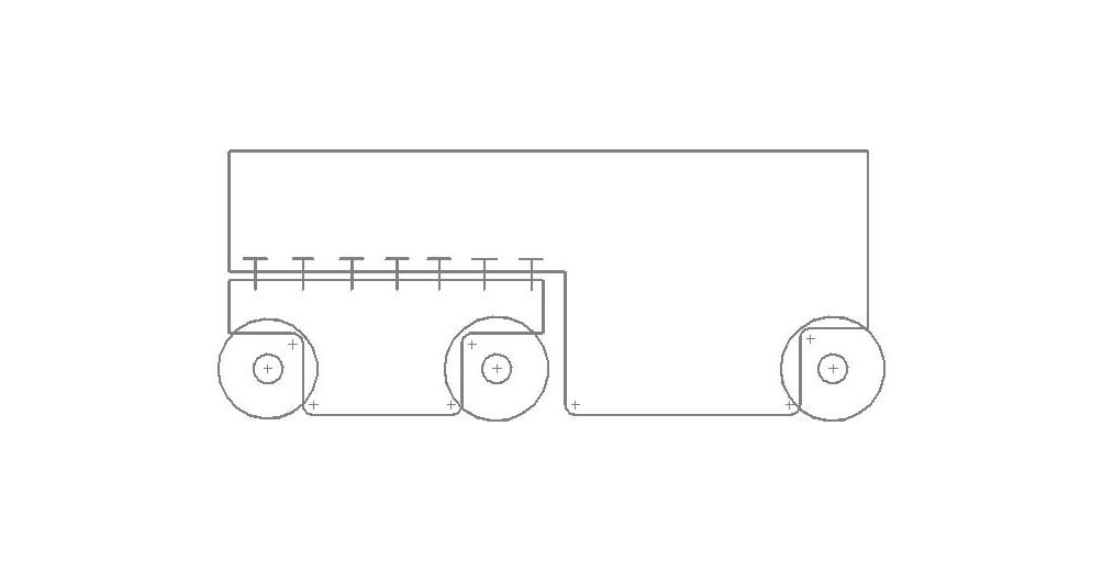
Additional wheel mounted in west side.
Wheel may affect by shock load during LT movement.
Hence it is not feasible
Proposal-3: Wheel mounded by hinge pin
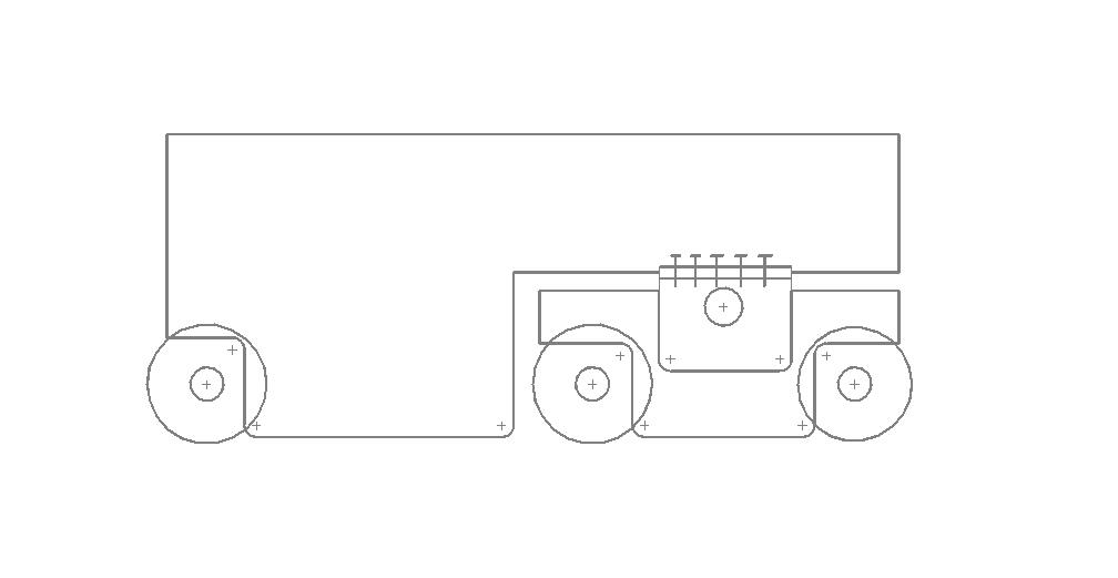
we have to install hinge mechanism for wheels to observe the track vibration.
Wheel replacing is easy.
It is possible and it can be implemented
3. Shaft calculation for changing design to 6 wheels while tilting operation.
Data:
- Total load: 135 tons
- Power: 75×10^3 W
- Speed: 1480 rpm
- Length: 0.320 m
- Material type: EN24T
To find:
We have to find the diameter of the shaft,
Te = (π/16) × Ʈ × d^3
1. Torque transmitted by shaft:
T= (P×60) / (2πN)
= ((75×10^3) × 60) / (2×π×1480)
T= 483.91 N-m.
2. Load carried by single wheel:
Load acts on 6 wheels: 30tones
Load acts on west side 4 wheels: 70tones +35 tones = 105tones
Load acts on single wheels: (30/6) + (105/4) = 31.25 tones
W= 31.25×1000×9.81
W= 306562.5 N
3. Bending moment:
Mь= W× (L/2)
= 306562.5× (0.320/2)
Mь= 49050 N-m
4. Equivalent twisting moment of shaft:
Te= [Mь^2 + T^2] ˆ ½
= [(49050)^2 + (483.91)^2] ˆ½
= 49052.38705 N-m
Te= 49052387.05 N-mm.
5. Shear stress calculation:
From PSG design data book Pg.no:1.15
For material EN24T,
Yield strength (σy) = 600 N/mm^2
Ʈy = σy/2
= 600 / 2
Ʈy = 300 N/mm^2
Factor of safety= 2.3
Ʈ = Ʈy / FOS
= 300/2.3
Ʈ= 130.43 N/mm^2
6. Diameter of the shaft:
Te = (π/16) × Ʈ × d^3
49052387.05 = (π/16) × 130.43 × d^3
d^3= 2698056.23
d= 124.19 mm
d~ 130 mm.
When FOS is 3.3 d = 140 mm
Shaft diameter Evaluation:
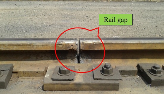
After installing 6 wheels, Shaft diameter 140mm is enough at the time of tilting operation. Wheel design changed from 4 wheels to 6 wheels. but track vibration can occur during travelling operation. This vibration will create shock load on wheel shaft. It will leads to shaft failure.
So, we have to install hinge mechanism for wheels to observe the track vibration.
We have decided to calculate the diameter of the hinge pin shaft.
4. Hinge pin calculation for new design.
Data:
- Total load: 135 tons
- Power: 75×10^3 W
- Speed: 1480 rpm
- Length: 0.320 m
- Material type: EN24T
To find:
The diameter of the shaft
Te = (π/16) × Ʈ × d^3
1. Torque transmitted by shaft:
T= (P×60) / (2πN)
= ((75×10^3) × 60) / (2×π×1480)
T= 483.91 N-m.
2. Load carried by single wheel:
Load acts on 4 wheels: 30tones
Load acts on west side wheels: 70tones +35 tones = 105tones
Load acts on single wheels: (30/4) + (105/2) = 60tones
W= 60×1000×9.81
W= 588600 N
3. Bending moment:
Mь= W× (L/2)
= 588600× (0.320/2)
Mь= 94176 N-m.
4. Equivalent twisting moment of shaft:
Te= [Mь^2 + T^2] ˆ ½
= [(94176)^2 + (483.91)^2] ˆ½
= 94177.24328 N-m
Te= 94177243.28 N-mm.
5. Shear stress calculation:
From PSG design data book Pg.no:1.15
For material EN24T,
Yield strength (σy) = 600 N/mm^2
Ʈy = σy/2
= 600 / 2
Ʈy = 300 N/mm^2
Factor of safety= 2.3
Ʈ = Ʈy / FOS
= 300/2.3
Ʈ= 130.43 N/mm^2
6. Diameter of the shaft:
Te = (π/16) × Ʈ × d^3
94177243.28 = (π/16) × 130.43 × d^3
d^3= 3677380.67
d= 154.34 mm
d~ 160 mm.
The required diameter for the hinge pin shaft is 160mm.
Also read: Simplify the Belt Conveyor Maintenance with 5 Essential implementations.
In addition that, We have to change the shaft material to avoid the keyway damage problem.
From Design Data Book:
| DESCRIPTION | EN 09 (C55Mn75) | EN 19 (36CrNi1Mo4) | EN 24T (40Ni2Cr1Mo28) |
| C | 0.50-0.60% | 0.36-0.44% | 0.35/0.45 |
| SI | 0.05-0.35% | 0.10-0.40% | 0.10/0.35 |
| MN | 0.50-0.80% | 0.70-1.00% | 0.40/0.70 |
| S | 0.06 Max | 0.040 Max | 0.040 max |
| P | 0.06 Max | 0.035 Max | 0.035 max |
| Cr | – | 0.90-1.20% | 0.90/1.30 |
| Mo | – | 0.25-0.35% | 0.20/0.35 |
| Ni | – | – | 1.25/1.75 |
| Tensile strength N/mm2 | 720-780 700-850 | 775-925 | 800-1550 |
| Yield stress N/mm2 | 460 | 555 | 600-1300 |
| Hardness HB | 170-255 min | 223-277 min | 229-444 min |
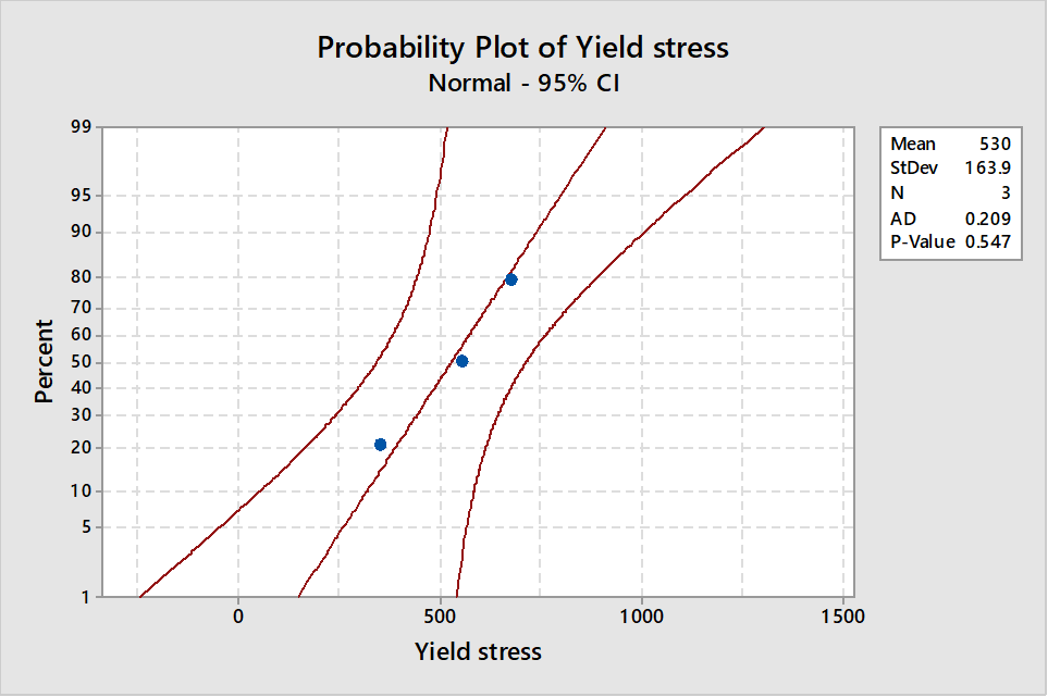
Yield stress of shaft material is a vital element for maximum life cycle. Since EN9 material has a very low yield stress compared to other material. Hence decided to replace the shaft material with EN24T.
Properties of EN24T Material
| Density | 7840kg/m3 |
| Youngs modulus | 207×109 N/m2 |
| Shear modulus | 80 Gpa |
| Thermal conductivity | 41.9 W/m-°C |
| Tensile strength | 80-155 Kgf/mm2 |
| Yield stress | 60-130 Kgf/mm2 |
| Bulk modulus | 140 Gpa |
Analysis by using ANSYS software
Vibration Analysis For LT Shaft
Shaft diameter-140mm, Length-450mm, Vibration time: 0-10 sec, Vibration: 0.05 – 0.24 HZ
Hinge Pin Load Analysis
Hinge pin diameter-160mm,Length-450mm,Load: min 30 T – max 60 T
Action :
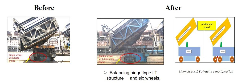
Results:
Previously, around ten LT wheel shaft failures occurred per year due to this issue. The modifications were implemented in December 2025. Since implementation, no further failures have occurred to date, and the availability of the Quench Car for operation has also improved.
Cost Savings
| Sl.No | Description | Calculation | Value |
| 1 | Hammer lifting failures per month | – | 10 failures |
| 2 | Time saved per failure | – | 60 minutes |
| 3 | Total saved time per year | 10 × 60 | 600 minutes |
| 4 | Approximate production delay considered per year | – | 600 minutes = 10 Hours |
| 5 | Daily coke production | – | 1,400 MT |
| 6 | Hourly coke production | 1,400 ÷ 24 | 58.33 MT |
| 7 | Metallurgical coke price per MT | – | ₹30,100 |
| 8 | Production value per hour | 58.33 x 30,100 | ₹17.55L |
| 9 | Estimated year production value for 10 hours | ₹1.7 Cr |
Note: The estimated production value based on 10 hours of avoided production delay.
Conclusion
The design calculations were completed by considering the combined bending and twisting moments, along with the additional loads acting on the Quench Car cage. Based on the calculations, the wheel arrangement was modified from four wheels to six wheels to distribute the load more effectively. A balancing hinge mechanism was also designed for the LT wheels to improve load distribution during the cage-tilting operation. In addition, the LT shaft material was proposed to be changed from EN09 to EN24T to improve its strength and resistance to recurring shaft failures. These modifications were planned to improve the reliability of the Quench Car LT system and reduce wheel shaft failures.
Also read: Wrench Time Analysis: How We Reduce Stamping Hammer Lifting Time from 45 to 21 Minutes