These Improvements Can Reduce Your Hydraulic Maintenance Burden in Industries
I am working in the Coke Manufacturing division of a steel plant from last 11 years, where hydraulic equipment is used throughout the production process. We observed frequent equipment failures and longer maintenance times. To address these issues, we initiated several small modifications to improve equipment reliability and reduce maintenance time.
I have shared details of five modifications that have proven useful at our plant. These tools are easy to fabricate and were developed in-house with the support of our technicians. The details provided here can be used for horizontal deployment across similar hydraulic equipment and as a benchmark for maintenance improvement activities in other plants.
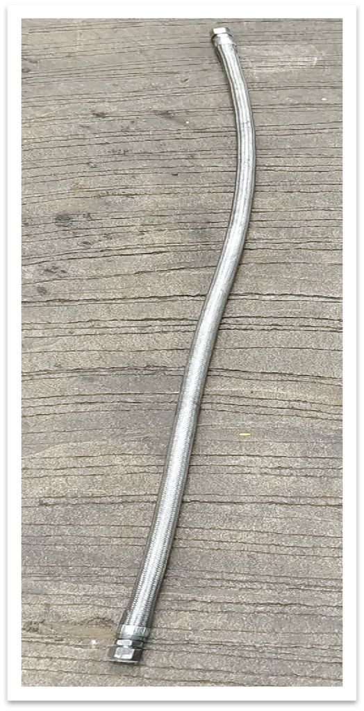
1. Usage PTFE (Polytetrafluoroethylene) Hydraulic Hose Braided with flexible 304 Stainless Steel in heat applications.
In the pusher car and quench car mobile door mechanisms, three hydraulic cylinders are operated. Initially, rubber PTFE hoses were used for these cylinders. However, the hoses were continuously exposed to heat radiation from the coke oven, resulting in hose deterioration and bursting during cylinder operation.
After replacing the existing hoses with steel-braided hoses, hose failures were eliminated. Additionally, hydraulic oil temperature was better controlled, and cylinder seal failures were reduced, improving the reliability of the equipment. This type of hoses continuously handles temperatures from -55°C to +210°C.
The hose failure reduced from 8nos / Year to 2nos / Year.
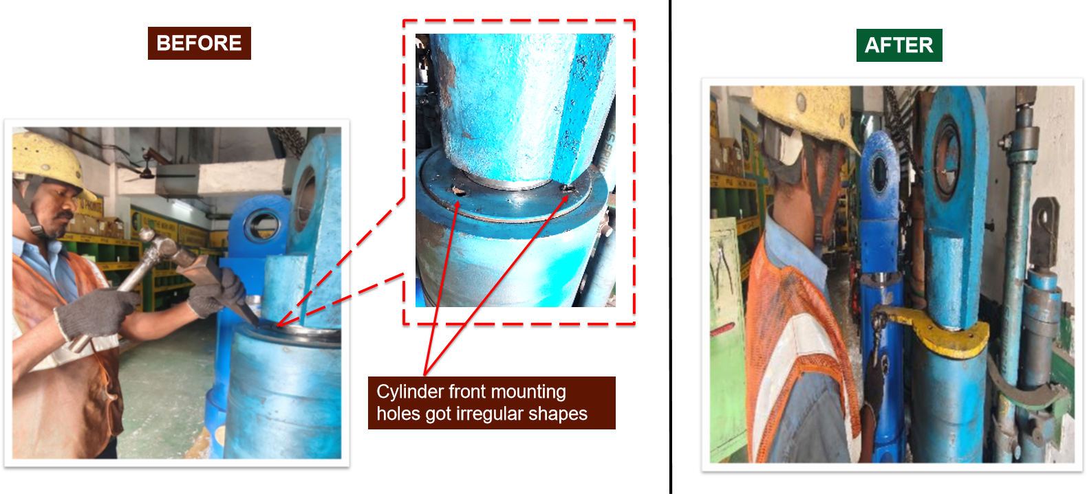
2. A modified jig arrangement was used for removing the small size cylinder cap mountings
During hydraulic cylinder servicing, the front cap is commonly removed using a chisel and hammer. Our team also followed this practice when servicing our machine cylinders. However, the repeated impact force from hammering could damage or deform the cylinder front cap.
To prevent this type of damage, I initiated a modified tool arrangement. The extended ends of the tool engage with the slots on the cylinder front cap, allowing the cap to be removed by rotating the tool instead of hammering. This tool can be fabricated in-house using available resources and workshop facilities. The attached video demonstrates its working method.
The cylinder front cap mounting removing time reduced from 30 min to 10min.
Before video :
After video:
3. A modified spanner arrangement was used for removing the big size cylinder cap mountings
During the servicing of this large cylinder, the front cap was removed using the conventional chisel-and-hammer method. The sharp edge of the chisel was inserted into the slot on the cylinder front cap and struck with a hammer. This method can damage the cylinder cap.
We introduced an internally fabricated spanner tool made from a 20 mm-thick plate, with two bolts provided to match the depth of the cylinder cap slots. These bolts are inserted into the slots, and the spanner is hammered to remove the cylinder cap mounting.
Here, a hammer was also used, but the impact force was not directly transmitted to the front caps of the cylinders. Therefore, the cylinder seals were protected from direct impact forces, reducing the risk of seal damage.
4. A Hydraulic oil separated with water by filtration system.
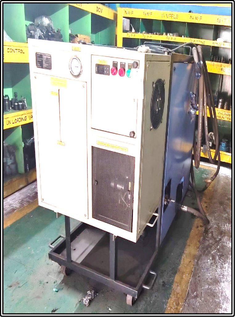
We have a quench car that is one of the most critical equipment in our plant. Approximately 35 tonnes of hot coke are carried by the cage assembly, which is operated by four large hydraulic cylinders. During the hot coke quenching process, water can enter the hydraulic cylinders through the scroll marks on the cylinder surfaces and mix with the hydraulic oil. Over time, this water contamination affects hydraulic operation and causes corrosion in the valves and cylinder parts.
Every time we can not replace the oil newly so we procured the LVDH 600 Low Vacuum Dehydration Unit to remove moisture and contaminants from hydraulic oil.
The Low Vacuum Dehydrator (LVDH) Model 600 is designed for hydraulic oil dehydration and moisture removal, with an overall moisture removal capacity of below 500 ppm. The system operates on a 415 V ±10%, 3-phase, 50 Hz, 4-wire electrical supply and is controlled by a PLC-based control panel with fault annunciation.
It is equipped with a 50 L/min discharge pump operating at 1–1.5 kg/cm², driven by a 0.75 HP, 3-phase motor. The vacuum system uses a 100 L/min belt-driven vacuum pump with a 0.5 HP motor operating at 1,400 RPM, along with a 50-litre balancing tank. The unit has a 50-litre nominal heating chamber fitted with a low-watt-density heater rated at 6 kW, 415 V AC, suitable for continuous operation.
Conclusion
These maintenance practices have been implemented in our plant. The tools were fabricated in-house based on our site conditions and equipment requirements. These modifications help make maintenance work easier and reduce the risk of damage to equipment components during servicing. Other plants can also adopt similar practices by fabricating tools according to their specific equipment designs, dimensions, and operating conditions.